
VIRMAK LLC
Welcome!!!
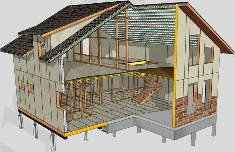
This instruction will allow you to get acquainted with the stages of assembling our kit houses to make sure that it is quite easy to construct your future house.
Most of our assembly units and materials included in prefabricated houses - are unique developments of the VERMAK company team. We have invested a lot of time, effort and funds in the modification of technology with an ultimate goal that you to get the most advanced products. This is the service life of your building (more than 80 years), environmental friendliness, energy efficiency, and what is most importantly - it's about the same budget (cost) in comparison with much more outdated prefab-houses of competitors.
OUR HIGH-TECH PRODUCT IS FOR YOU!!!
We recommend using these instructions for self-assembly together with a catalogue of assembly units developed by architects and engineers of our company!!!
The catalogue of assembly units is provided with the purchase of a kit house!
STAGE 1. Installation of foundation mat on piers or reinforced-concrete base
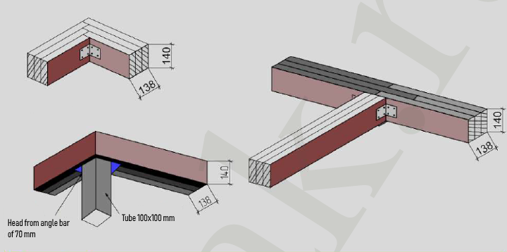
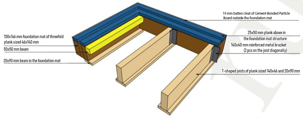
The timber foundation mat has a cross-section of 140x138 mm (or other specified linear dimensions at the request of customer). Also, for ease of installation, the foundation mat has all the appropriate grooves for connecting to each other and at the corners.
To prevent decay of wood, the foundation mat is treated with a bituminous primer from the bottom and covered with cement-bonded particle board from the outside. Fabrication of foundation mat and processing is performed at the VERMAK factory.
|
Hardware for assembling the foundation mat: Screw 7,5x202 mm, Screw 100x12 mm; Screw 100x5 mm; Self-tapping screw 4x40 mm; L-bar 70x70 mm |
|
Necessary tool: Screw driver, drill, hammer, ratchet handle, tape measure 50 m |
- Before installation on piles, it is necessary to lay a roll waterproofing (Linocrome).
- All corners of the connection are to be reinforced with metal brackets and screws.
- Secure the foundation mat on the pile caps with screws from below.
- Check the horizontal position of the laid foundation mat (starting bar), diagonals at the outer corners of the foundation mat and then proceed to the installation of boarding joists.
- If you have a girder foundation, then lay the starting bar on the waterproofing layer.
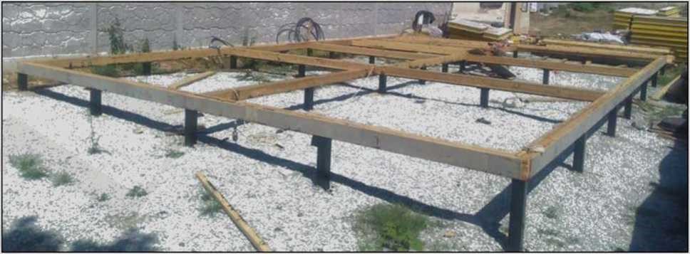 Fig. 1 The foundation mat assembly
The frame of foundation mat and floor joist:
Note: All the beams of foundation mat are manufactured and marked individually for each building, according to the VIRMAK assembly chart.
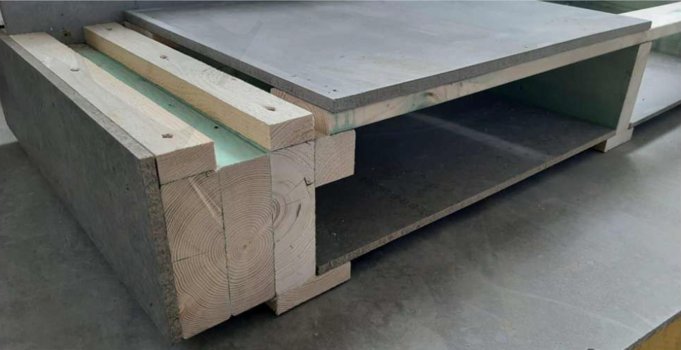
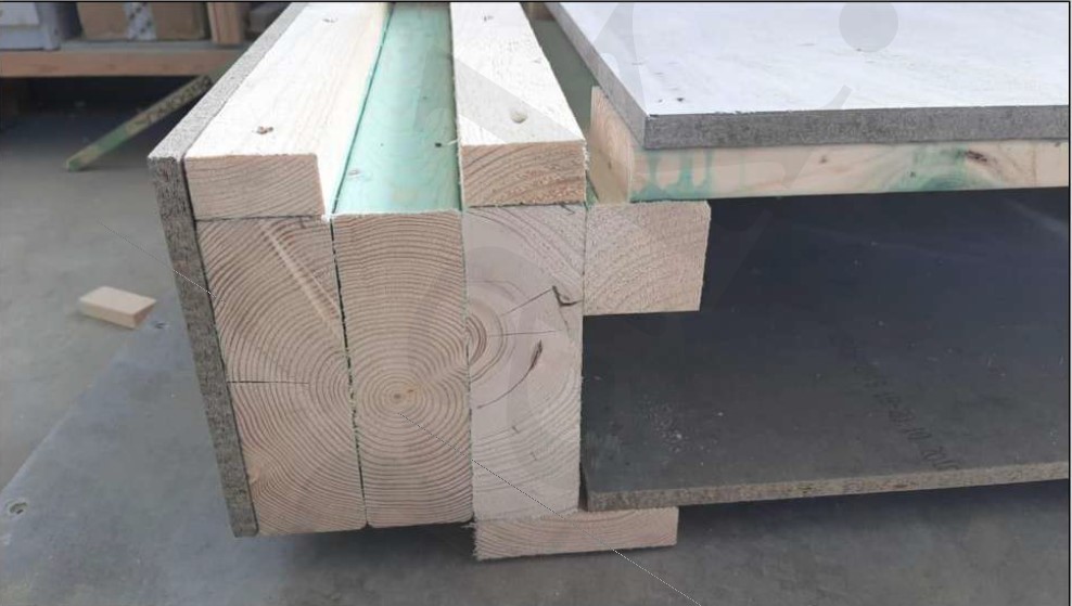
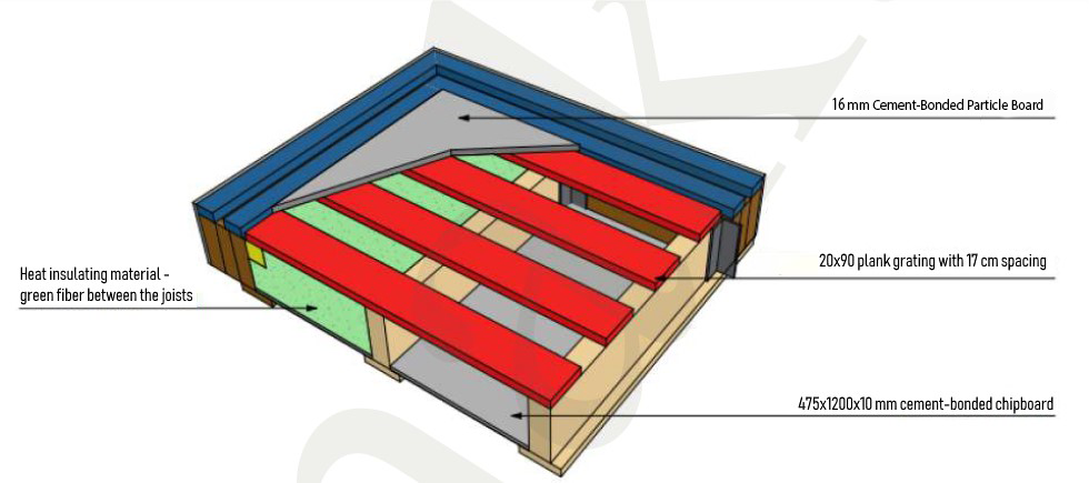
STAGE 2. Installation of wooden floor joists and grating
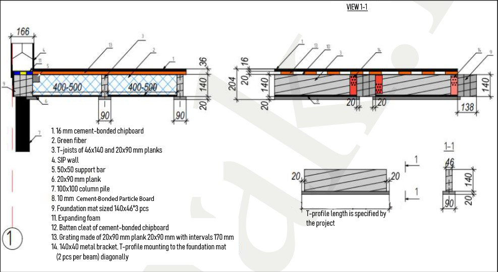
The main frame ground level floor consists of:
- T-shaped joists of the floor (with 400-500 mm intervals);
- bottom layer of cement-bonded particle board;
- intermediate layer - insulation between the floor joists made of green fiber based on fiber glass or basalt;
- the upper grating of a 20x90 mm plank (with 170 mm intervals);
- upper solid flooring made of 16 mm cement-bonded particle board.
|
Hardware for the assembling of the frame floor: 140x40 mm reinforced metal bracket; 5x90 mm screw; 4x40 mm self-tapping screw; |
|
Necessary tool: Screw driver, drill, hammer, ratchet handle, tape measure 50 m |
- First, install the T-shaped joists of a floor (the bottom of which is treated with bituminous primer) that are manufactured in size according to the individual project at the VERMAK factory. The joists are secured with reinforced 140x40 mm metal brackets and self-tapping screws to the foundation mat in the same plane with it. The intervals are indicated on the floor plan.
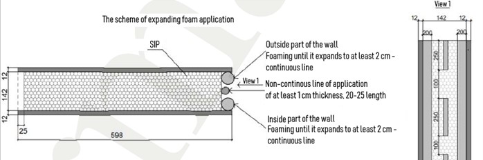
- Lay the 10-12 mm cement-bonded particle board on the flanges of T-shaped joists between the beam spans and secure them with expanding foam. In this case, the expanding foam performs a double function: adhesive and thermotechnical, removing the so-called "thermal bypasses".
- Assemble the 20x90 mm grating at 170 mm intervals across the floor joists, starting from inside of the foundation mat. Secure it with 2 self-tapping screws on each cross joist.
- The heat insulation between joists and laying of 16 mm cement-bonded particle board solid flooring is to be made after sheltering the house (installation of a roof).
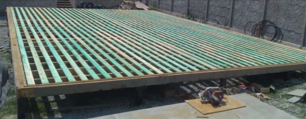 Fig. 2 Ground level floor assembly (without insulation and finishing solid covering of cement-bonded particle board)
The frame of foundation mat and floor joist:
 Note:
Note:
- All the floor joists are manufactured and marked for each building individually, according to the VIRMAK company assembly chart;
- All lumber shall be treated with bio-based flame retardants;
- All cement-bonded particle board joints are sealed with vapor-permeable filling material.
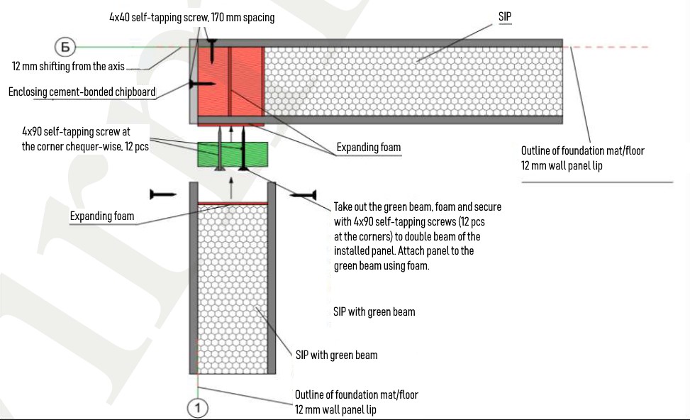
STAGE 3. Installation of external wall panels
Three-layer external wall panel consists of:
two sheet enclosing cement-bonded particle board of 12 mm
internal thermal insulation layer with a thickness of 142 mm of two types: PSB-25 polystyrene (with 25 kg/m3 density) or ISOVER mineral wool board (with 64 kg/m3 density).
|
Hardware for assembling SIP walls: 50x50 mm metal bracket; 5x90 mm screw; 4x40 mm self-tapping screw; expanding foam |
|
Necessary tool: Screw driver, hand sledge, 1 m water level gauge, wood circular saw |
When installing the foundation mat, the starting beam of the walls is already made as a solid structure and secured on top of the foundation mat beams.
- Having first foamed, the wall panel is installed on the fixed starting beam of the foundation mat without additional hardware.
- Install the first 2 panels that form the corner of the house:
The corner assembly consists of three connecting posts. Fix the connecting bar and then install the second corner panel. In a house kit the VIRMAK company attaches the so called batten cleat made from cement-bonded particle board to one of the corner SIPs to prevent locking of wooden stay beam in the SIP.
Note:• Special attention should be paid to the verticality of the installation. Vertical panels are to be mounted directly at a 90-degree angle to each other.
- The SIPs with the cement-bonded particle board are secured with expanding foam and self-tapping screws through preliminary counter formed holes in the cement-bonded particle board (see the diagram below). Installation diagram for the first corner of the house:
 1st corner installation
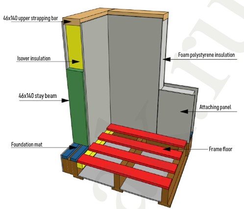
- Further panel assembly is performed according to the project drawings due to the assembly chart. All panels are marked according to the size and type of fabrication framing. During installation, it is necessary to leave a thermal gap of 3-4 mm between the panels.
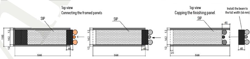
- Assemble the below and above the window panels as shown in the drawing.
- After mounting all the walls, place a 46x140 mm strapping bar in the upper groove of the panels. The bar is dipped into the wall panel by 20 mm and, accordingly, it protrudes by 26 mm, since it is also the "starting" bar of the second floor SIPs.
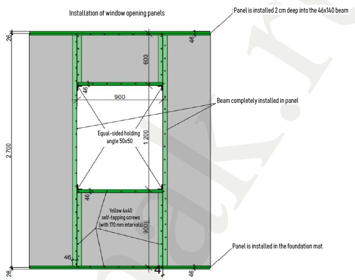
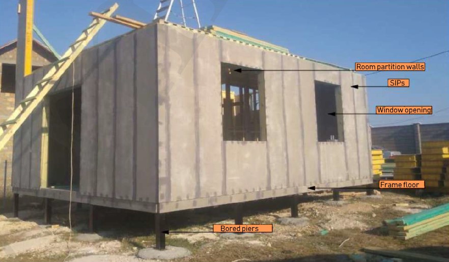 Fig. 3 The first floor walls assembled
STAGE 4. Installation of room partition walls
The VIRMAK company recommends to produce room partition walls from regularized chamber dried timber.
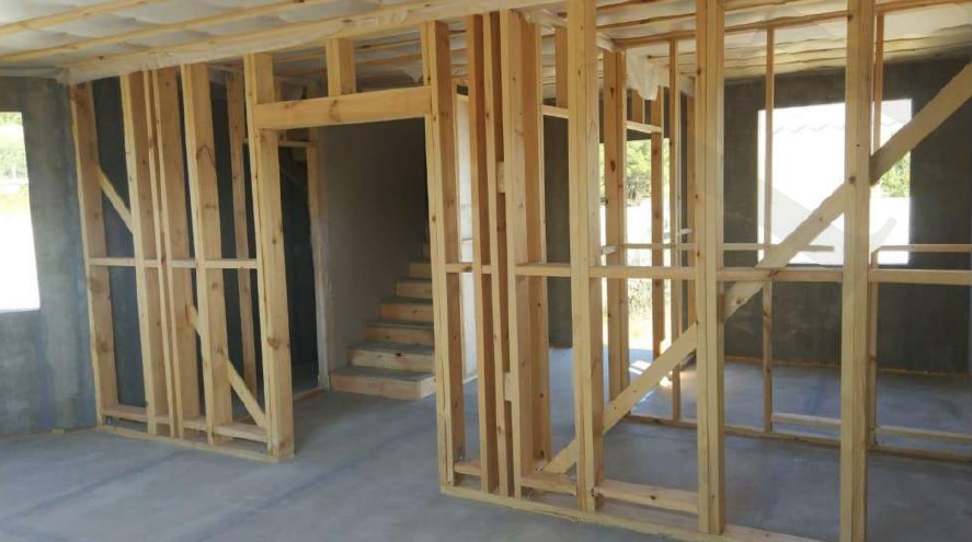
 Fig. 4 Room partitions
This decision was made for two reasons:
- arranging of hidden engineering communications. - excellent noise absorption, using various acoustic mats of different density, and various sheet, enclosing material, such as gypsum wallboard, gypsum-fiber sheet, and cement-bonded particle board.
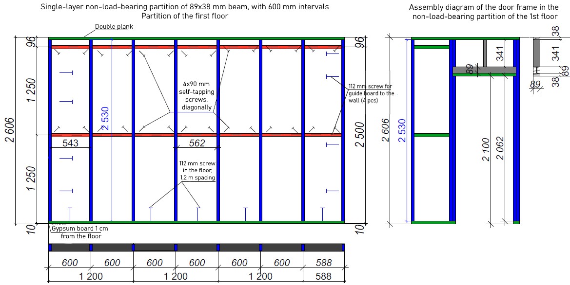
Installation of partition walls is carried out according to the assembly chart and does not arise any difficulties. 38x89 mm cross beam is double in load-bearing partitions, and single in non-load-bearing partitions as you can see in the photo.
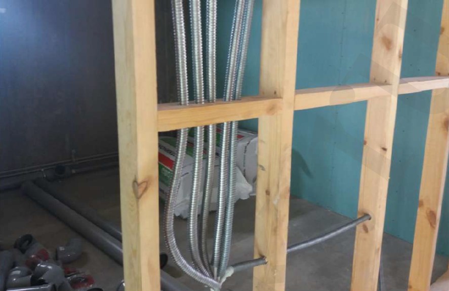
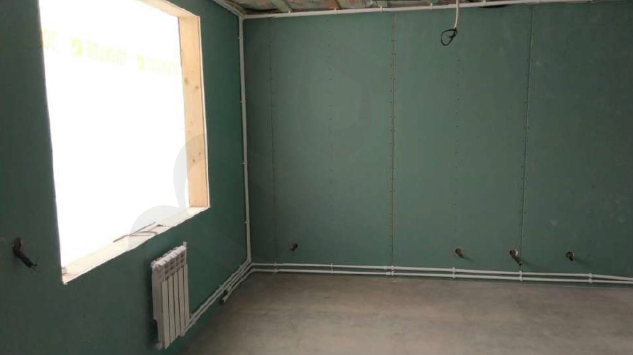 Fig. 5 Partitions with laying of communications
|
Hardware for assembling SIPs: 50x50 metal bracket; 5x90 screw; 4x40 self-tapping screw; expanding foam |
|
Necessary tool: Screw driver, 1 m water level gauge, wood circular saw, staple gun and tape ruler |
Diagram of load-bearing and non-load-bearing partitions:
Partitions for two-story house

Note:
All lumber shall be treated with bio-based flame retardants
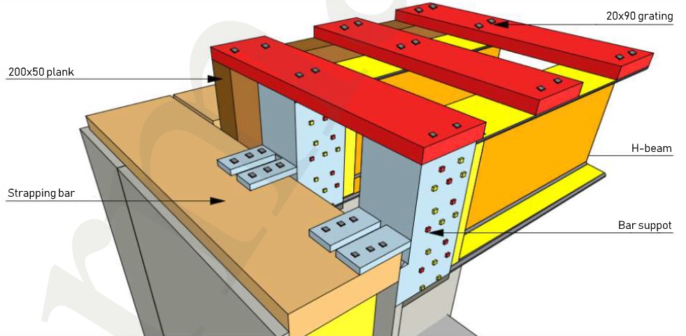
STAGE 5. Installing intermediate (exploitable) floors
The intermediate floor consists of structural wooden H-beams (the beams interval is usually 600 mm, as determined by the project). The beams are mounted on the wall panels by means of feature bar supports. The bar supports are attached to the upper protruding strapping bar of the first floor SIPs.
|
Hardware to assemble the intermediate floor: 200x80 H-beam support; 5x90 mm screw; 4x40 mm self-tapping screw; 112 mm screw ; left and right support |
|
Necessary tool: Screw driver, 1 m water level gauge, wood circular saw, staple gun, tape ruler |
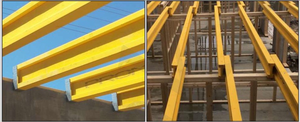 Fig 6. Installation of bar supports and floor beams on external and internal walls
 Installation instructions:
- Lay 200x80 mm H-beams on top of the interior frame partitions. Fasten them to the capping of the frame partition with 5x90 mm self-tapping screws. Make sure that H-beams joint falls directly on the support in the SIP walls and support of the frame partition.
- It is necessary to pin a 200x50 mm board to the wall in parallel to the H-beams with 112 m wood screws spaced at intervals of 60 cm. It is important to get into the vertical strut of the SIP wall. This is the end of the floor deck installation.
- Using 20x50 mm grating we attach a vapor barrier film to the beams from below in 20 cm increments. Blow green fiber in space between the beams (with consumption of 13 kg per 1 m2 of the floor).

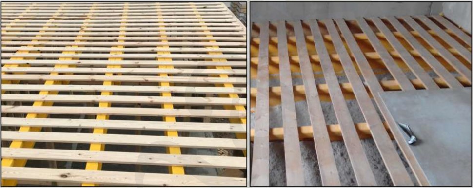 Fig. 7 Installing the upper grating
Fig. 8 Installing acoustic insulation and solid covering from 12 mm cement-bonded particle board
- • Laying of solid sheet material on the floor deck (cement-bonded particle board) and acoustic isolation are possible only after the housetop and roof covering will be mounted (prevention of getting wet).
- • All lumber shall be treated with bio-based flame retardants.
STAGE 6. Installation of the wall SIPs at subsequent storeys
Installation of the second and subsequent floors panels is made according to the same procedure as for the first floor. The only difference is that the guide - starting bar is already there - it is the top strapping bar of the first floor. One floor is mounted on another floor.
|
Hardware for assembling SIPs: 50x50 mm metal bracket; 5x90 mm screw; 4x40 mm self-tapping screw; expanding foam |
|
Necessary tool: Screw driver, 1 m water level gauge, wood circular saw, staple gun and tape ruler |
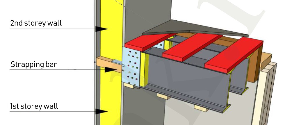
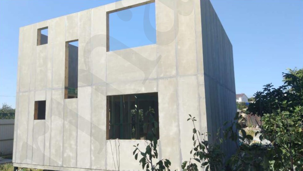 Fig. 9 The walls of two storeys assembled
- • If the second or subsequent floors are of the attic type, then the top strapping bar becomes a wall plate for mounting the roof.
STAGE 7. Installation of the roof system
The process of housetop and roof covering installation doesn't differ from the installation of a non-SIP houses: brick or block one. It is all the same: joists and rafters, usually with the 1st grade natural moisture board of 150x50 mm cross-section, film, grating. Roofing - finishing material: metal shingle, asphalt shingle, metal profiles, etc.
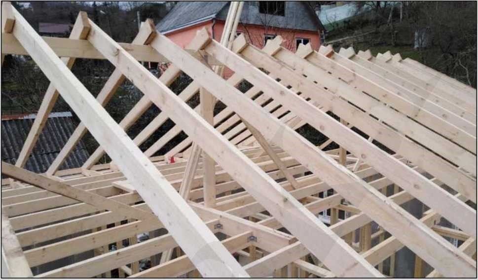
Insulation of the attic floor is to be made with green fiber between 150x50 mm joists, respectively, with a layer thickness of 150 mm.
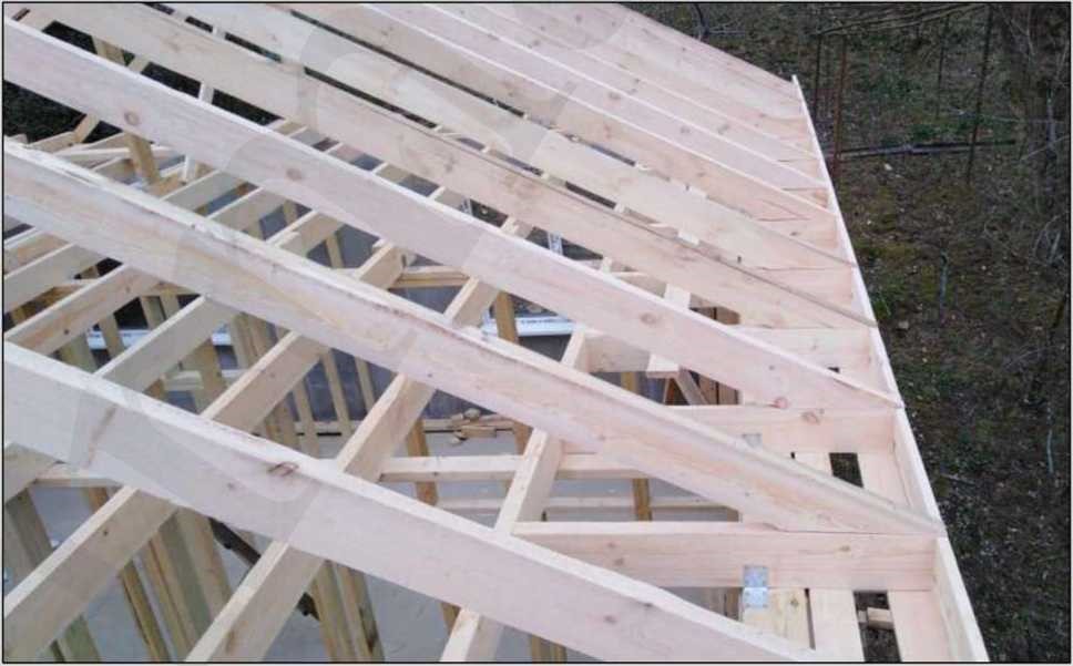 Fig. 10 The attic floor and rafter system
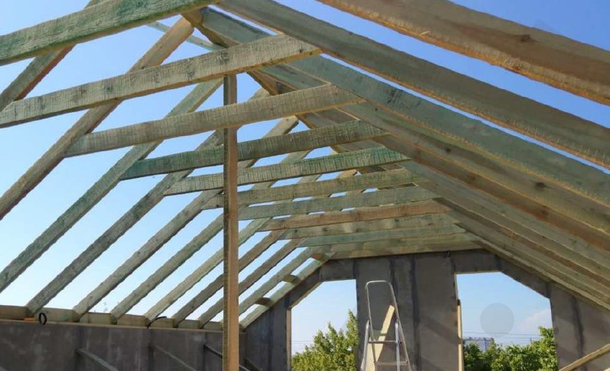
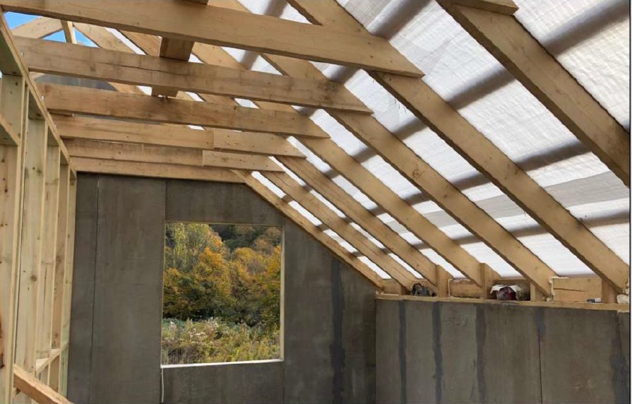 Fig. 11 Rafter system of attic type
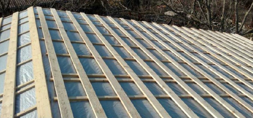 Fig. 12 Wind and water protection and roof sheathing
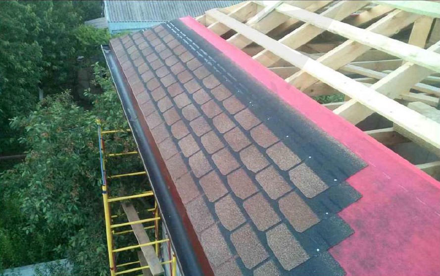 Fig. 13 Underlay covering and flexible shingles
Insulation of the mansard roof is made by roll or plate thermal insulation materials on the side slopes of the roof and between the binding beams showed in Fig. 11.
The SIP roof is assembled similarly to the SIP walls - the procedure with same requirements.
|
Hardware for assembling the roof: 70x70 mm metal bracket; 5x90mm screw, 4x40 mm self-tapping screw; 100x50 connecting plate; left and right rafters mountings, left and right bar supports (additional hardware is possible depending on the project) |
|
Necessary tool: Screw driver, wood circular saw, staple gun, tape ruler, hammer |
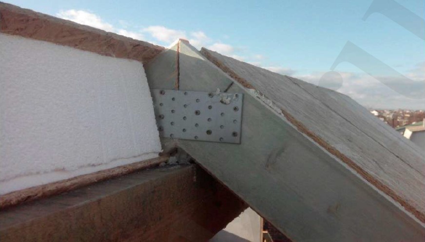 Fig.14 Ridge joint of roof panels
At the photo you can see the VIRMAK company's solution: a roof made of SIPs without a ridge beam for rolled roofing material. The ridge board in Fig. 10 plays a temporary "supporting" function. Having made grooves at the roof panels and boards at an angle, we remove the ridge beam. Panels are fixed due to pressure on each other.
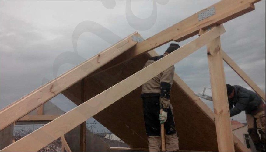 Fig. 15 Ridge joint of the roof panels with the use of ridge beam and cross beams
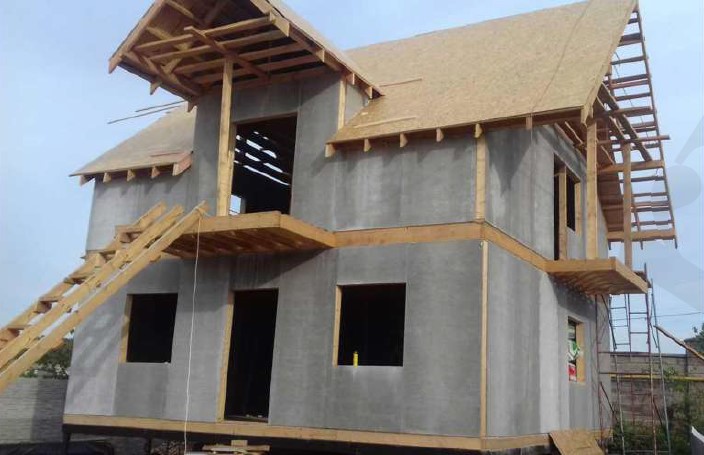
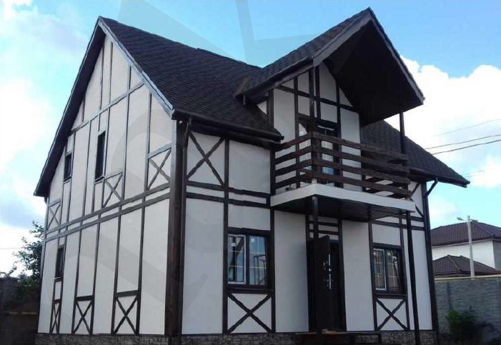
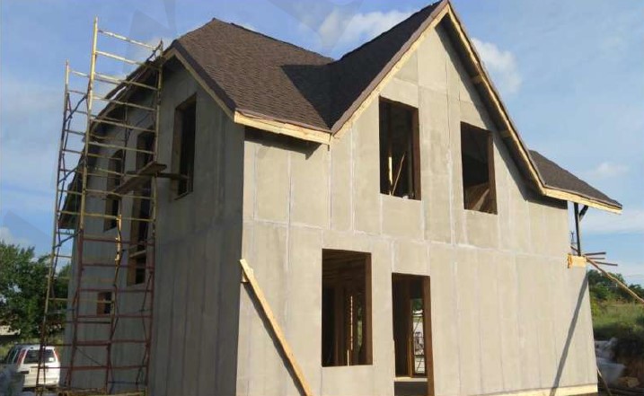 Fig. 16 The roof with flexible tile covering
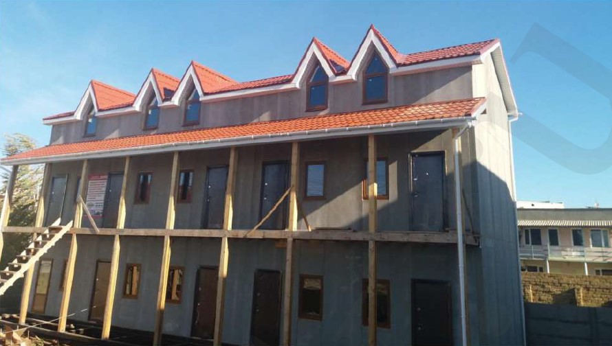
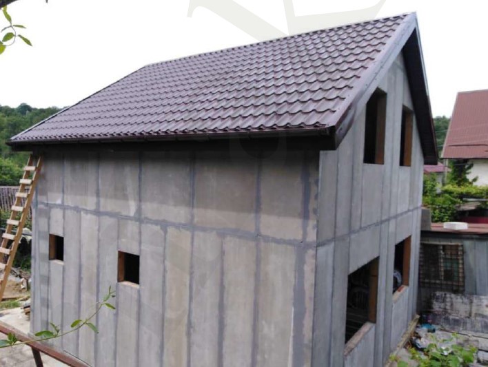 Fig. 17 The roof with metal tile covering